
Series Circuits
In a series circuit components like resistors and loads are connected in a single path. Current must go through every component in order starting from the positive terminal of the battery through everything in order and back to the negative battery terminal.
Series Circuits vs. Parallel Circuits
Series Circuits only have one path while parallel circuits we will see in a later unit have branches. Compare the pictures below each with three resistors.


Lights in a Series Circuit Compared to a Parallel Circuit
When lights are connected in a series circuit and one goes out the circuit becomes open and no other light works. This is because there is no path to the negative terminal of the battery when a circuit is open.
When lights are connected in parallel circuit and one light goes out the remaining ones stay on. No current will flow down the branch with the disconnected light bulb since that branch is open. Current will follow the other paths to the negative terminal of the battery leaving the other lights on.


Series Circuit Diagrams
To keep the models simple we will only places a battery and resistors in the circuits of our diagrams on this page. Remember that the longer line in the battery symbol is the positive terminal and the shorter line is the negative terminal. The convention is to have current run from the positive terminal to the negative terminal. Due to this convention the resistors are numbered in order. Here the resistors get their number resistor 1, resistor 2, and resistor 3 based on the flow of current starting from the positive terminal of the battery.
Series Circuit Rules
Voltage Drop In A Series Circuit
In a series circuit voltage drops across each resistor until the entire amount provided by the battery has dropped. If you add all the individual voltage drops of a series circuit together you can determine the voltage of the entire circuit (VT) found at the power source.
Current in a Series Circuit
There is only one path in a series circuit for current to travel on. All current must run from the positive terminal to the negative terminal of the power source. Observe the animation of how the same current has to flow through every component of the circuit in series.

Resistance in a Series Circuit
Any resistor or load (device with a resistance) in a series acts like a speed bump in a series slowing current down. Since there is only one conductive path in series every device adds to total resistance.
Note that a wire itself has resistance and the less conductive a wire is the more resistance it would add to a circuit. We will ignore this in our examples below for simplicity and pretend the wire was 100% conductive.


Circuit Equations
Ohm’s Law (V=IR), Voltage equals current times resistance, can be used anywhere in the circuit but only at a single location.
See all the squares in red above, if you are using Ohm’s law you can only use information in that location, the V,I, and R within a single square.
The location can be an individual resistor, for example resistor one with the variables Voltage (V1), Current (I1), Resistance (R1). The location can also be at the battery, which is a measure that represents the overall circuits voltage (VT), current (IT), and Resistance (RT).
At the battery the subscript T (ex. VT) stands for total or of the circuit. Some equations sheets may use emf (ex. Vemf) or another notation, if there is any subscript other than a number it will likely be of the circuit.
When you are using information between different red blocks you must use the series circuit rules.
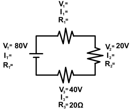
Start any problem by drawing out the circuit and have every resistor labeled as you see in the picture above. Then write in all your givens. Next, follow the basic steps to a series circuit problem.
Basic Steps To A Series Circuit Problem
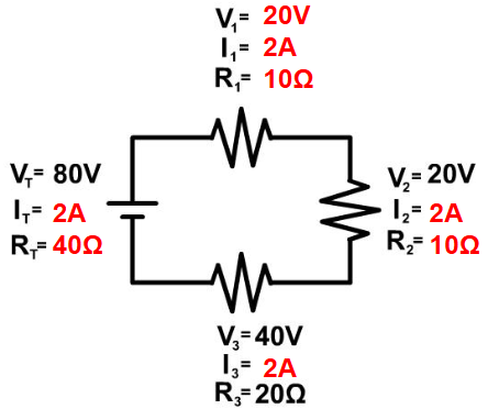
IT = I1 = I2 = I3 = …
VT = V1 + V2 + V3 + …
RT = R1 + R2 + R3 + …
You will continue to follow these steps over and over until everything in the circuit is complete. Follow our examples below until you feel comfortable to follow the steps solving series circuit problems on your own.
Example Problem 1

Example Problem 2
Note: While our example stick to whole numbers for simplicity, this would be very uncommon and you would normally have decimals. Do not be shocked if you have decimals, just make sure all the rules are followed and do a final check as presented in the examples below.

Example Problem 3

Some problems as the one seen below are drawn showing multimeters taking the reading of the current as seen below. This is not part of the circuit and is just taking a reading.
You would rewrite the problem above taking out the multimeters and placing the readings into the problem and start the problem as seen in example 4 below.
Example Problem 4
Try example 4 on your own and click “See Solution” to check your answers.
Another Way Current Can Be Given In A Series Circuit Problem
Be aware that current can also be drawn into a problem in the wire and not at a single resistor. This is not an additional resistor but seeing the current drawn as a circle over the wire shows you the current in that wire. Since there is only one wire going from the previous resistor to the new resistor, you know in series both of those must have that current as well. See the picture to see a visual of this.

Circuit Construction Kit
The following PhET circuit construction kit can help you understand the workings of circuits more.
Links
- Continue to Parallel Circuits
- Back to the Main Current and Circuits Page
- Back to the Stickman Physics Home Page
- Equation Sheet