
Parallel Circuits
A Parallel circuit includes branches providing multiple paths for current to flow. In the last unit we covered series circuits which only had one path. Look at the pictures below to see the difference.
Parallel Circuit Handout to go along with the problems on this page and the PhET lab at the end.


Because of branching, additional paths for current, when light bulbs are in parallel and one goes out the others remain on.
- Parallel Circuit: If one light burns out the others stay on
- Series Circuit: When one light burns out the others go out


Parallel Circuit Rules


Circuit Equations
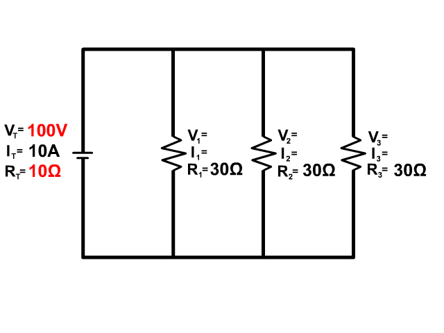
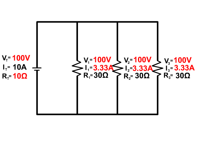
Ohm's Law (V=IR), Voltage equals current times resistance, can be used anywhere in the circuit but only at a single location.
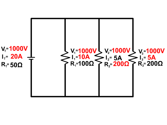
See all the squares in red above, if you are using Ohm's law you can only use information in that location, the V,I, and R within a single square.
The location can be an individual resistor, for example resistor one with the variables Voltage (V1), Current (I1), Resistance (R1). The location can also be at the battery, which is a measure that represents the overall circuits voltage (VT), current (IT), and Resistance (RT).
At the battery the subscript T (ex. VT) stands for total or of the circuit. Some equations sheets may use emf (ex. Vemf) or another notation, if there is any subscript other than a number it will likely be of the circuit.
When you are using information between different red blocks you must use the parallel circuit rules.
VT = V1 = V2 = V3 = …
IT = I1 + I2 + I3 + …
1/RT = 1/R1 + 1/R2 + 1/R3 + …
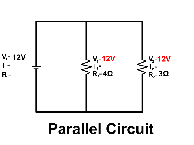
Voltage in a Parallel Circuit
Since electrons are free in a conductor the entire region in light red in the picture share the free electrons equally. The voltage completely drops equally from the entire voltage provided from the positive terminal of the battery across all resistors in parallel to the other side with the negative terminal. because of this:
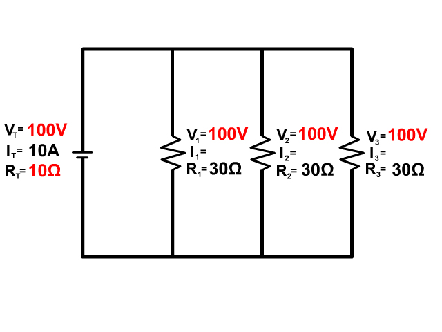
VT = V1 = V2 = V3 = …
The entire voltage drops equally an the entire amount through all resistors in parallel. Because the voltage along each branch is equal to that provided to the branch, equal to the power source.

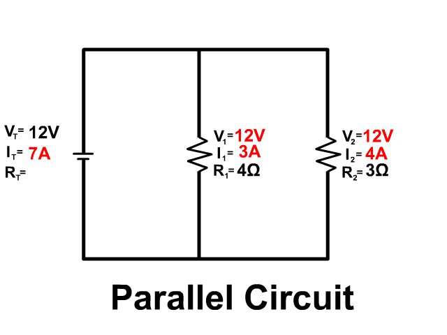
Current in a Parallel Circuit
Current flows like water through a parallel circuit separating down branches and coming back together. The amount of current flowing down each branch depends on that branches resistance. The entire current provided by the battery is equal to the sum of current going down each branch.
IT = I1 + I2 + I3 + …

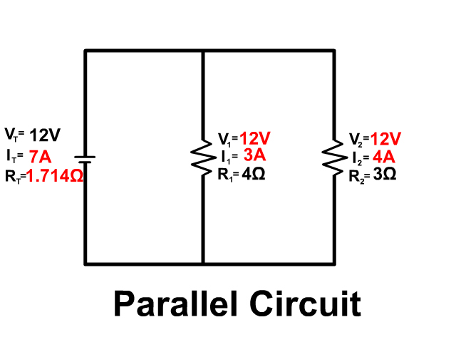
Resistance in a Parallel Circuit
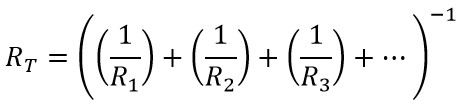
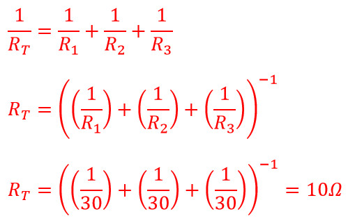
Resistance in a parallel circuit is unique. In order to add a resistor in parallel you also have to add another path for current to follow. Because you add another path, you decrease resistance and therefore increase current. The relationship between resistors in parallel can be determined using the following equation:
1/RT = 1/R1 + 1/R2 + 1/R3 + …
Adding a resistor and path makes it easier for current to flow. To determine the total resistance the equation above rearranges to:
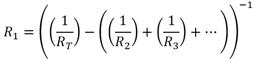
To find an individual resistor this equation would rearrange to:
The total resistance in parallel will always be less than the lowest resistor.

Basic Steps To A Parallel Circuit Problem
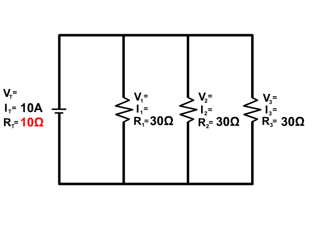
#1 See if you can do Ohm's Law (V=IR) at any location in the circuit.
#2 See if you have voltage anywhere because that voltage will be the same everywhere following the parallel circuit rule below.
VT = V1 = V2 = V3 = …
#3 Check if you can do any of the other parallel circuit rules.
IT = I1 + I2 + I3 + …
1/RT = 1/R1 + 1/R2 + 1/R3 + …
You will continue to follow these steps over and over until everything in the circuit is complete. Follow our examples below until you feel comfortable to follow the steps solving parallel circuit problems on your own.
Example Problems
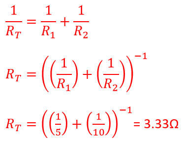
1. What is the resistance of a 5Ω and 10Ω resistor in parallel?
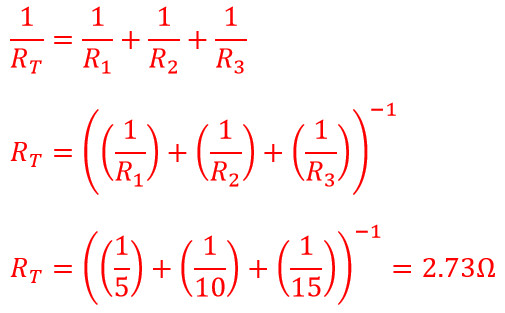
2. What is the resistance of a 5Ω, 10Ω, and 15Ω resistor in parallel?
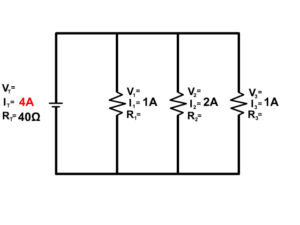
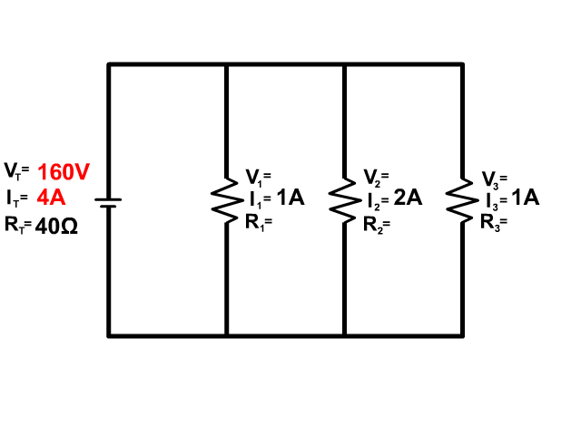
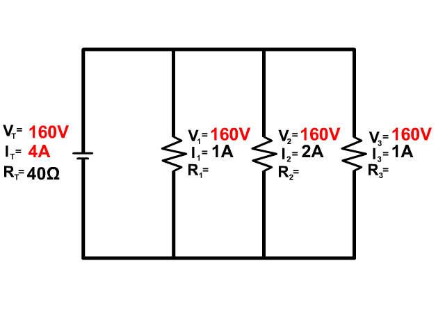
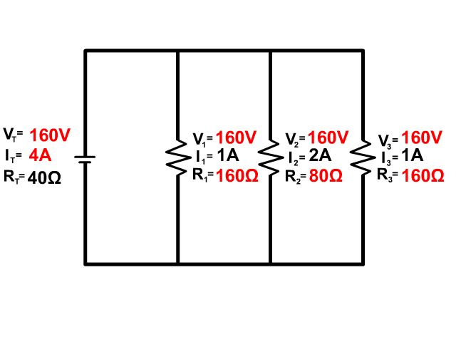
3. Solve for all the components of the parallel circuit using the information given.


4. Solve for all the components of the parallel circuit using the information given.

5. Solve for all the components of the parallel circuit using the information given.

6. Solve for all the components of the parallel circuit using the information given.

Circuit Construction Kit
The following PhET circuit construction kit can help you understand the workings of circuits more.
CLICK HERE FOR THE PARALLEL CIRCUIT LAB SHEET
Go to the following website is the embedded version is not working
Links
- Continue to Batteries and Lights
- Back to the Main Current and Circuits Page
- Back to the Stickman Physics Home Page
- Equation Sheet