Lenses and Ray Diagrams
Curved lenses use refraction to bend light and produce an image that can be a different appearance than an object being observed.
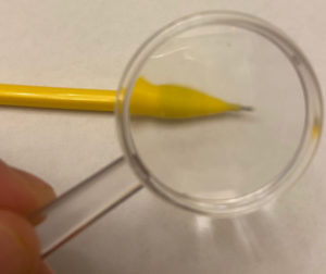
Lens Terms
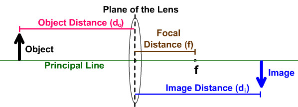
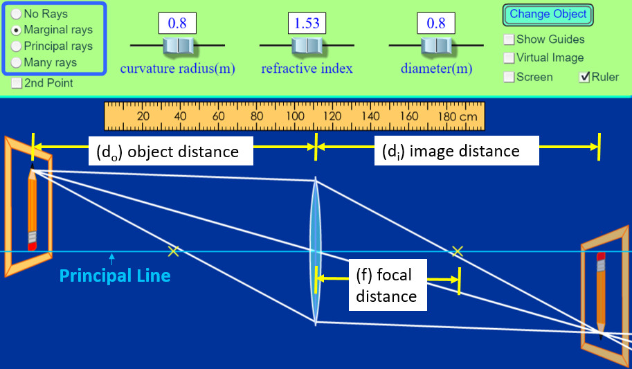
(do): Object Distance: distance from the lens to the object
(di): Image Distance: distance from the lens to the image
(f) Focal Distance: distance from the lens to the focal point of the lens
Principal Line: horizontal line perpendicular to the plane of the lens
The first basic lens type is a convex lens:
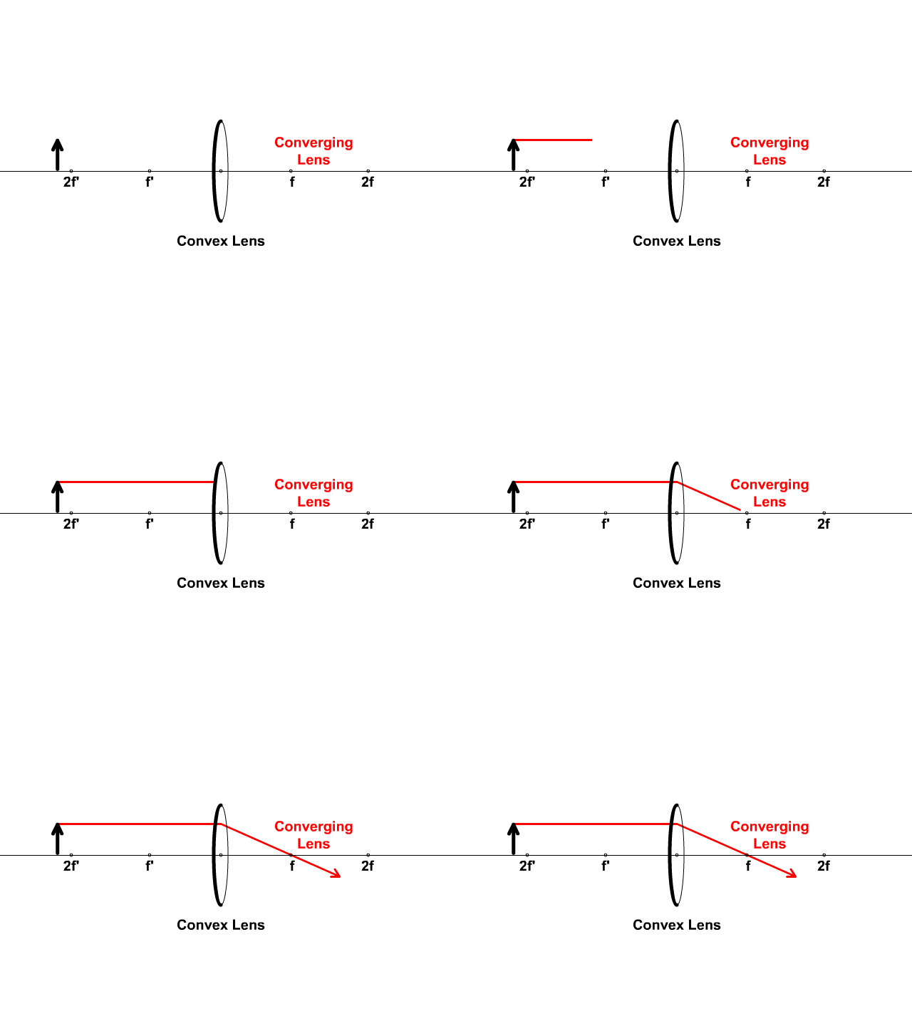
Called a Convex Lens based on its shape and also called a converging lens when referring to how light rays bend through.
Convex Lens
- Named for the shape of the front side of the lens
- The lens curves away from the object
- Just look at the front side (the actual lenses we draw in our pictures are called double convex since both sides bend similarly)
Converging Lens
- Light refracts, bending inwards toward the center principal line
- Converging means that light is coming together
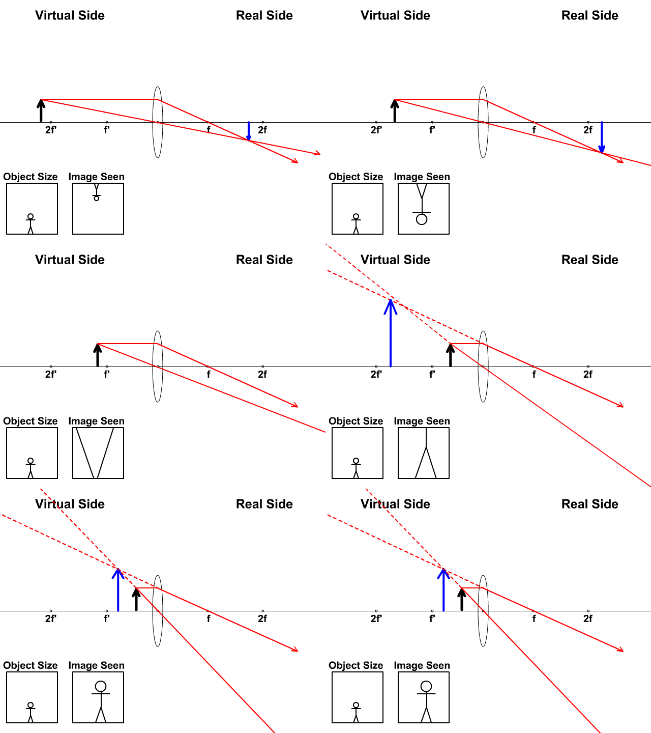
Convex Lenses Produce
- Real or Virtual Images
- Inverted or Upright Images
- Enlarged or Reduced Images
- Directly at the focal length, no image is produced before the image flips
Ray diagrams we will draw later help us determine the image produced.
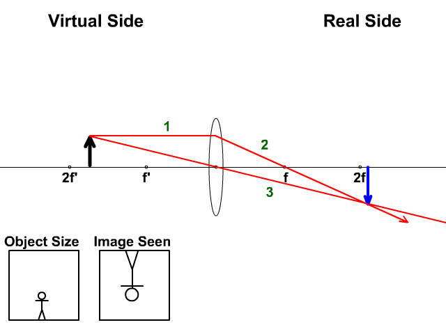
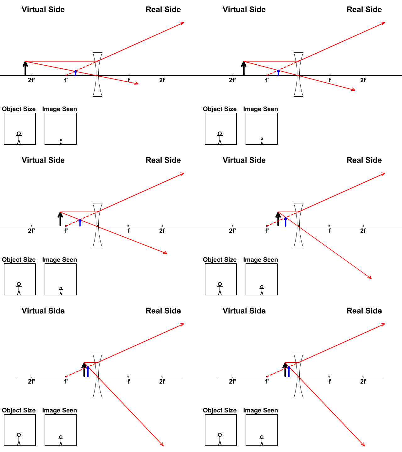
The black thick arrow represents the object located a distance from the lens. The blue arrow represents the image produced. The two boxes with a stickman helps you understand the difference between the object and the image.
The other basic type of lens is a concave lens:
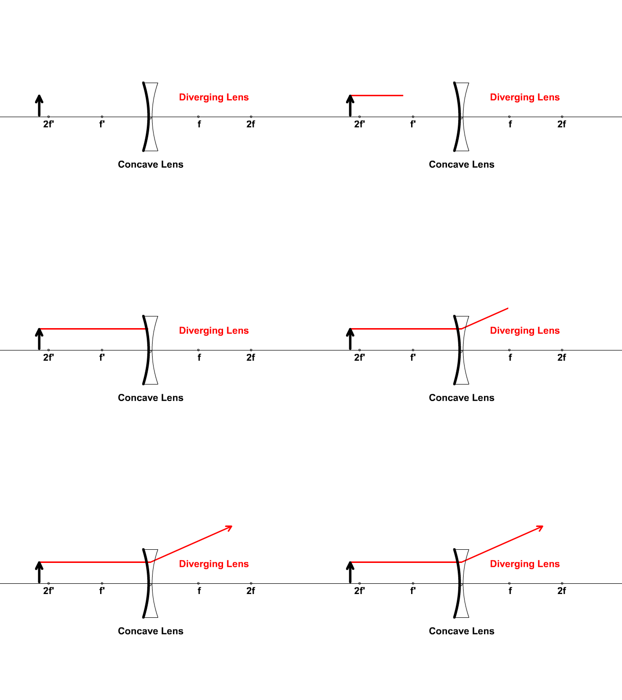
Called a concave lens based on its shape and also called a diverging lens when referring to how light rays bend through.
Concave Lens
- Named for the shape of the front side of the lens
- The lens bends away from the object
- Just look at the front side (the actual lenses we draw in our pictures are called double concave since both sides bend similarly)
Diverging Lens
- Light refracts, bending outwards away from the center principal line
- Diverging means that light is spreading out
Concave Lenses only produce
- Virtual Images
- Upright Images
- Reduced Images
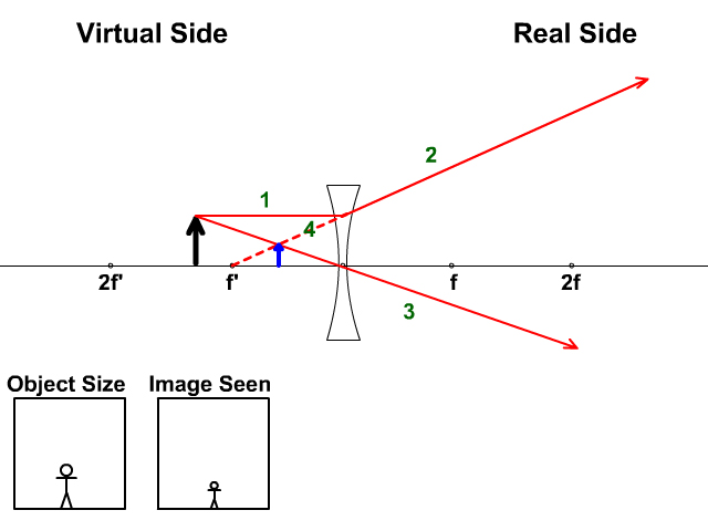
Observe how the image is always upright and reduced. A reduced image because its always smaller than the object.
Fact: Because virtual images cannot be projected. A camera or projector that needs an image projected will always use a convex lens.
Virtual and Real Sides of a Lens
As we approach the math we will do later it is important to understand a few things about lenses.
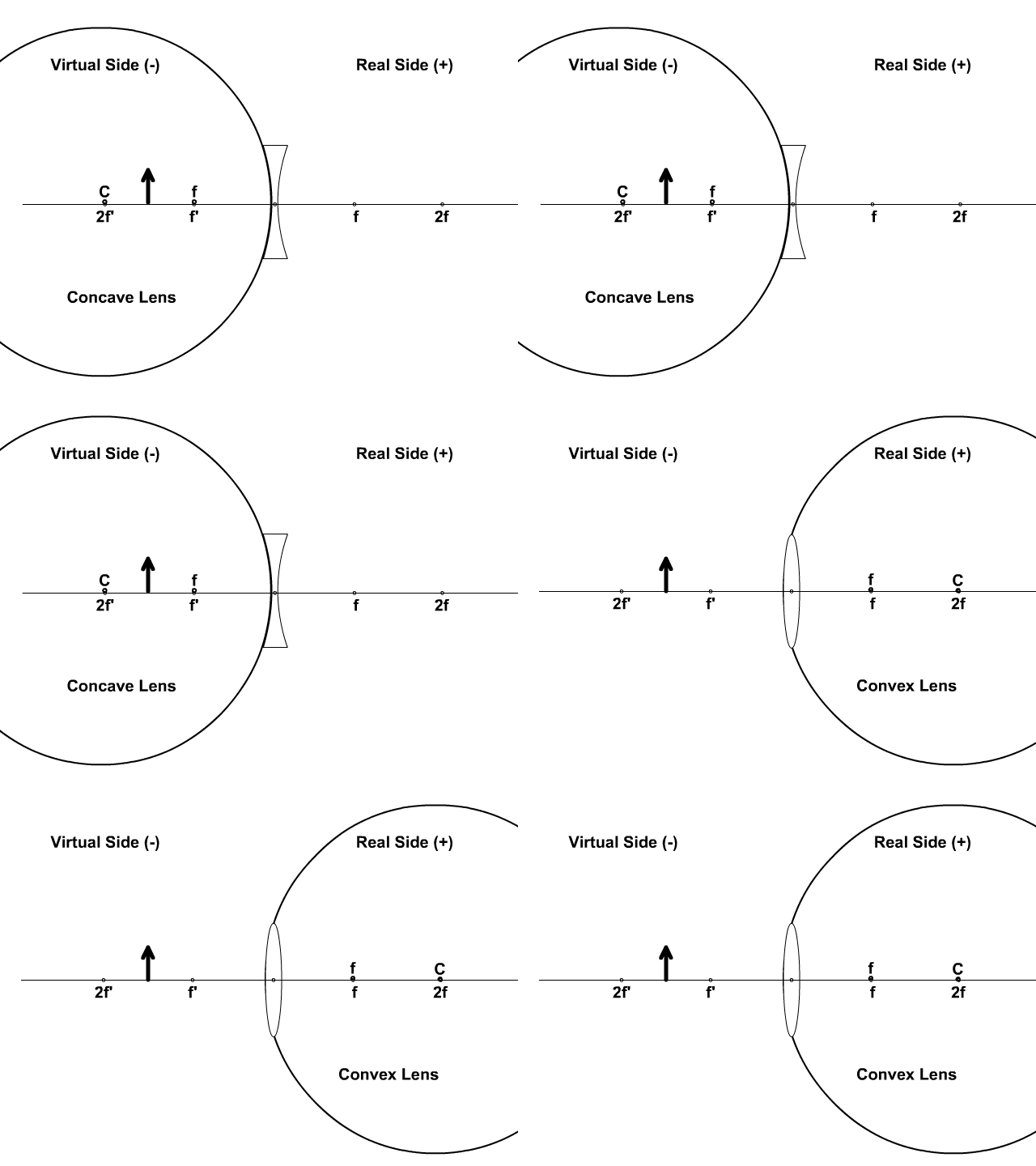
Light travels through a lens unlike a mirror. Since light is expected to travel through a lens the real side is on the opposite side of the object. The object is represented by the thick black upright arrow.
With lenses in preparation for math with lenses:
The object is always considered to be on the real side:
- do is always positive + when we get to the math
- concave lens: f is always negative -
- concave lens focal distances will be negative during math since the curve of the front side is toward the virtual side.
- convex lens: f is always positive +
- convex lens focal distances will be positive since the curve of the front side is toward the real side.
With mirrors the curve of the mirror bends toward a center of curvature. This is represented by (C). Half way to the center of curvature is the focal point (f).
With lenses the center of curvature is instead represented by a double focal length or (2f) but we still also represent the focal length as f.
- If the double focal length (2f) is 10 cm then the f would be 5 cm.
We use an apostrophe (') to represent the virtual side f' and 2f'.
Steps to a Concave Lens Ray Diagram
- Start the First Ray: Start with your pencil on the top of the object (black thick arrow tip) and draw a line parallel to the principle axis to the center of the lens. Keep your pencil on the paper here
- Line up a ruler with the (f') focal point and the center of the lens where your pencil is at. Draw a line away from the (f') focal point to the real side of the lens and place an arrow tip on the end.
- Start the Second Ray: Line up your ruler with the top of the object and the center point of the lens on the principle axis. Draw a line all the way from the tip of the object straight through the center of the lens to the other side. Draw an arrow tip on the end.
- Use a ruler to follow the arrow tip lines back to the virtual side of the lens. Where the two lines cross the object appears.
- Draw the object top where the rays intersect. Draw the base of the image arrow (blue in the picture) to the principle line.
Now analyze your image drawing compared the the original object:
- It is virtual (on the virtual side of the lens)
- upright (the top is up, and if the image is upright it will always be virtual)
- it is reduced (The image arrow is smaller than the object arrow)
Concave lenses will only produce, virtual, upright, reduced images


Steps to a Convex Lens Ray Diagram
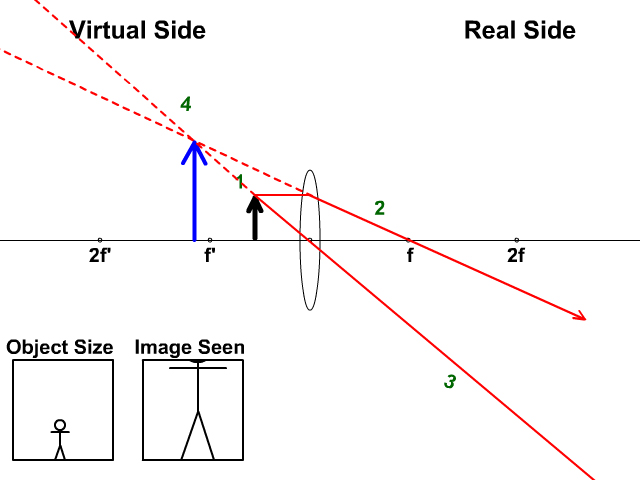
Look below and not at the animation to see the numbered steps for two scenarios and the analysis of the image produced.
- Start the First Ray: Start with your pencil on the top of the object (black thick arrow tip) and draw a line parallel to the principle axis to the center of the lens. Keep your pencil on the paper here
- Line up a ruler with the (f) focal point and the center of the lens where your pencil is. Draw a line towards and through the (f) focal point on the real side of the lens placing an arrow tip on the end.
- Start the Second Ray: Line up your ruler with the top of the object and the center point of the lens on the principle axis. Draw a line all the way from the tip of the object straight through the center of the lens to the other side. Draw an arrow tip on the end.
- Use a ruler to follow the arrow tip lines back (If they meet on the real side, you do not have to extend the lines to the virtual side. If not draw the lines to the virtual side of the lens. Where the two lines cross the object appears.
- Draw the object top where the rays intersect. Draw the base of the image arrow (blue in the picture) to the principle line.
Now analyze your image drawing compared the the original object:
- It is real (on the real side of the lens)
- inverted (the top is down, and if the image is inverted it will always be real)
- it is enlarged (The image arrow is larger than the object arrow)
Now analyze your image drawing compared the the original object:
- It is virtual (on the virtual side of the lens)
- upright (the top is up, and if the image is upright it will always be virtual)
- it is enlarged (The image arrow is larger than the object arrow)

Now get some practice drawing and analyzing lens ray diagram images.
- Download the Lens Ray Diagram Worksheet
- Use the video to check or get extra help on this worksheet
PhET Lens Interactive Lab
Use the picture as a guide to review the variables asked about in the lab.
During the lab you can:
- Change the focal point length by changing the curvature radius
- Alternatively change the focal point by changing the refractive index. This changes the medium of the lens and thus the amount of bending (refraction).
PhET Lab measurements
- Measure (do) by clicking on ruler and using it to measure from the pencil to the lens
- Measure (di) by using the ruler to measure from the lens to where the image appears
- Measure (f) by using the ruler to measure from lens to the x on the right side representing the focal point.
Return here when you have completed your Lens Math Lesson and complete the following lab:
(Note: some lens ray diagrams follow three rays as seen in the lab interface but the end result is the same)
Link to the Lens PhET lab on their website here: https://phet.colorado.edu/en/simulation/geometric-optics
Links
- On to Lens Math and Equations
- Back to the Main Electromagnetic Waves Page
- Back to the Stickman Physics Home Page
- Equation Sheet

