
Circuit Basics
In this section you will learn the basic terminology of a circuit. This includes common objects that make up a circuit and their symbols.
What is Current?
Before looking at circuits and basic terminology it is important to understand what current is. Current is a flowing or moving charge.
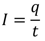
The variables in this equation are current (I), charge (q), and time (t).
MKS unit for current is the Ampere (unit A)
1 Ampere (1A) of current means one coulomb of charge passes per second
Water and Electricity Analogy
When you think of electricity you can compare it to the flow of water, a common analogy.
- Voltage, the potential to flow, Increases the further distance up.
- Resistance, the pushing back against flow, decreases if pipe width is bigger.
- Current, the actual flow, increases when voltage is high and resistance is low.

Less Resistance Allows More Current
What four components change the resistance of a wire?
- thickness
- length
- material
- temperature
Increases Resistance (Less Current)
- The thinner the wire the less electrons can flow
- The longer the wire the more distance from point A to point B
- The material of the wire, the lower conduction, the harder it is for electrons to flow.
- Higher temperatures increase resistance in a wire.
Decreases Resistance (More Current)
- The wider the wire the more electrons can flow
- The shorter the wire the less distance from point A to point B
- The material of the wire, the higher conduction, the easier it is for electrons to flow. Top Conductive Metal Elements (Silver, Copper, Gold, Aluminum)
- Lower temperatures decrease resistance.

Common Symbols Used In A Circuit
Battery: A long line next to a shorter line. The long line represents a positive terminal (cathode) and the short line the negative (anode). The battery provides the source of electrons in a circuit. The convention is that current flows from the positive terminal to the negative.
Fuse: This is a safety device added to a circuit. When current is too high, heat from the current will melt the metal. This will open the circuit and the fuse will have to be replaced. A fuse can be rated for different currents. This protects from fire or equipment damage that could result from an excessive current.
Circuit Breaker: This is another safety device to protect from damage including fire with the same purpose as a fuse. When too much current is present the circuit will open. The circuit breaker must be manually reset to close the circuit again.
Load: This is any device the circuit can power. It can be a light, speaker, toaster oven, or anything else.
Resistor: This is a device specialized to slow down the current in a wire.
Open Switch: The symbol it two dots with a slanted open wire in the middle showing an open circuit.
Closed Switch: The symbol is two dots with a wire still connected in the middle showing a closed circuit.

Closed vs. Open Circuit
- A circuit must be closed to have electrons flow (current) and the load on
- A open circuit is off
- A closed circuit in on
Once a circuit is on:
- A potential difference (V) between two points creates an electric field
- An electric field moves through a circuit setting electrons in motion


Electron Drift
Electrons move slowly bouncing around in many directions as they gradually follow the direction of current. This random patter is called electron drift.
Heat is always a side effect of electric current (because of electron drift).

Direct Current vs. Alternating Current
Notice the additional symbols that are used to represent power sources in the picture. Outlets in most homes provide alternating current while most appliances use direct current. The process of turning AC into DC is called rectification. Rectification can be done using diodes. Diodes are electronic components that allow a flow to occur one way but not the other.
Power Sources
A battery always provides a direct current with conventional current flowing from the positive terminal to the negative.
A common outlet will have alternating current when you plug an appliance into the wall. Often there will be a rectifier to convert alternating current (AC) into direct current (DC) as many appliances require DC current.

What is the difference between direct and alternating current?
Direct Current (DC)
- Electrons move in one direction from where there are more electrons to where there are less
- The convention is to draw current from the positive terminal to the negative
**Note: the dots in the animation go with conventional current and not actual electron flow.

Alternating Current (AC)
- Electrons constantly change directions
- In USA, direction changes 60 times per second

Conventional Current
The conventional way to draw current is the direction of positive charge flow. This dates back to the mid 1700's. Benjamin Franklin theorized that positively charge particles has a positive fluid that flowed toward negative charged objects. Even after J. J. Thompson discovered the existence of the electrons, and today we agree electrons flow, the prior convention remains.
The convention in a circuit is to draw current from positive to negative.

Intro to Circuits Quiz
Circuit Construction Kit
The following PhET circuit construction kit can help you understand the workings of circuits more.
Go to the following website is the embedded version is not working
Links
- Continue to Electric Current
- Back to the Main Current and Circuits Page
- Back to the Stickman Physics Home Page
- Equation Sheet