
EM Wave Phenomenon
Learn about light coherence and alignment. Understand the electromagnetic wave phenomenon of polarization and diffraction.
Types of Light
White light that you see from a flashlight or the sun is incoherent with random patterns of all colors of light mixed. Crests of these waves do not align crest to crest and trough to trough.

Incoherent vs. Coherent Light
In the pictures below we use red light waves to see coherence. Red light produced from a flashlight with a filter would produce incoherent red light. The phases of the wave are random and don't line up.
A laser uses a crystal and power source to create constructive coherent monochromatic light. Monochromatic light means it has a single wavelength and color. Constructive interference occurs when the crests line up. Coherent since the light is consistently in phase. Lasers amplify the light produced due to constructive interference.


Alignment of Light
Light from a flashlight or the sun is unpolarized, aligning in many random polarization angles. Notice how the alignment varies in the picture here.

Polarized Film
Polarized film acts as a filter blocking light not aligned to the polarized films transmission plane. The polarized film in our animation has a horizontal transmission plane.

Two Sheets of Polarized Film
A vertical transmission plane will block 100% of light polarized horizontal or perpendicular to transmission plane. A horizontal transmission plane will block 100% of light polarized vertically.
When two sheets of polarized film are aligned parallel, similarly aligned light is allowed through both. You see little difference than using only one film.
When two sheets of polarized film are aligned perpendicular, they will filter out all light. You will not see through the film since they each filter out the light that the other does not.

How Polarized Sun Glasses Work
1. Light from the sun has random alignment as it travels into our atmosphere.
2. As light hits the horizontal ground or another horizontal surface it becomes polarized horizontally. We call this glare as it shines off the ground or an object ahead of you.
3. Sunglasses are polarized vertically, not allowing horizontally polarized glare through.
Polarized sunglasses allow you to see the incoherent light reflecting off most objects around you while cutting out distracting glare.

Example Questions
1. Which Set of sunglasses would cut out horizontally polarized glare?
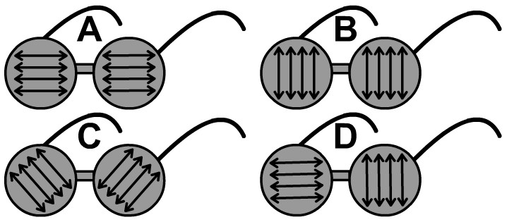
2. What would a person wearing the sunglasses labeled D above see when looking at horizontally polarized glare?
3. Why can you still see objects around you while wearing polarized sunglasses?
Huygen's Principle
Huygen's Principle is the reason why diffraction occurs in waves. Every Point on a wavefront acts as a source of a new wave. Because of Huygen's Principle a wave will bend as is goes around a corner.
In this animation we follow five points from the initial wave with each of the five points becoming the source of a new wave. In reality this occurring everywhere along the wavefront all the time and not just the five points pointed out by our model.

Diffraction and Wavelength
Diffraction is the property of a wave where it bends going around a corner or an opening, which has two corners. Longer wavelength waves diffract more than ones of shorter wavelengths do.
- As the wavelength increases, the angle of diffraction increases
- Angle of diffraction is directly proportional to the size of wavelength
In the electromagnetic spectrum radio waves have the largest wavelength and would diffract the most. Gamma rays would diffract the least.
In the visible light portion of the electromagnetic spectrum red, the largest wavelength of light, would diffract the most and violet the least.
Diffraction grating, a sheet with many slits for light to diffract through, can be used to separate out the colors of the rainbow from white light. Diffraction grating works to separate colors because different colors have different wavelengths bending at different angles.

Single Slit Diffraction
Wavelength is an important factor for determining the refraction after an opening. The larger the wavelength of a wave, the greater the diffraction.
A wavefront is an area of a wave that is in the same phase. The blue lines that appear after the aperture or opening in the animation represent wavefronts.
In this animation we break out three points and observe the diffraction occurring as they each act as a source of a new wave.

Red Single Slit Diffraction
The largest central area of light in single slit diffraction is called the maximum.
Red light has a larger wavelength than violet and would result in a wider diffraction. This wider diffraction leads red to have a greater maximum than violet when placed equidistant to the single slit and the screen that light is projected on.
Diffraction and interference leads to the pattern of bright and dark bands you see.
You can experiment with the single slit diffraction patterns resulting from color of light and aperture using the PhET lab at the bottom of this page.


Example Questions
4. Would orange or green light diffract the most and why?
5. Would radio waves or orange light diffract the most and why?

Use the provided single slit diffraction patterns produced by a green and red laser equidistant to a single slit opening and optical screen which captures the projection.
6. The middle larger area of light in the single slit diffraction pattern seen in the image is called a maximum. What is a reason why the red maximum is larger than the green maximum?
7. The brighter areas projected in single slit diffraction (labeled A in the image) are the result of what type of interference?
8. The darker areas projected in single slit diffraction (labeled B in the image) are the result of what type of interference?
Double Slit Diffraction
As monochromatic light is projected trough two slits. The further apart the slits, the greater the interference. So there will be more nodes (constructive interference) and antinodes sections (destructive interference) will get narrower. An optical screen can capture the resulting light pattern.

Double Slit Experiment
When light is shined through two openings or slits that are thin and close together you may expect to see only two spots projected. Because light is a wave you get a diffraction bending the light outwards. As light is bent outwards waves interfere. Wave interference lead to a pattern of lighter and darker spots resulting from constructive and destructive interference. Destructive interference where you see less or no light. Constructive interference where there is brighter light.

Wave Nature of Light
Through the double slip experiment you see two of the four properties that all waves share. Diffraction and interference results in the observed pattern of light. Reflection of light can be seen anytime you look in a mirror. Prisms and each water droplet of a rainbow act like prisms refracting and separating the colors of light.
Wave Interference PhET Lab
Use the PhET Simulation also found below and on the PhET site following this link to study wave interference.
Links
- On to the Mirrors Lesson
- Back to the Main Electromagnetic Waves Page
- Back to the Stickman Physics Home Page
- Equation Sheet